Wiring Harness Form Board Continuity Tester
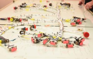
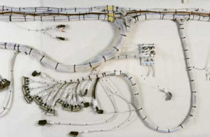
Building large wiring harnesses can be a bit challenging. By large i am talking about harnesses 10’s of feet long or more, with possibly dozens of connectors branching off at various places along the cable. To help with this task, often a full wiring diagram, printed to scale, will be placed on a table, so that technicians can have a visual aid when building the harness. This is often called a “form board”. Here are two examples of wiring form boards. Technicians will then gather around the table each wiring a different connector.
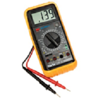
After the cables are built, a continuity test is usually performed. At the time the tool of choice for this task was a tester from Cirris Systems. These testers consist of 1000’s of relays in a switch matrix configuration, such that any input can be tested against any other input, for continuity and a wide range of other testing. They are programed to automatically verify that a cable is built properly. This beats having to perform a continuity test with a multimeter. The catch is that you need a way to connect the harness you just built to the tester. So you have to build another harness, often called a “back wire harness”, which has connectors to mate to all your main harness connectors PLUS what ever connectors are on the continuity tester.
So the main problem occurs when your final continuity testing of the harness indicates that there was an error in the wiring. As careful as the technicians are at building the harness its easy to miss wire something. Some connectors can have over 100 pins. By the time the harness is completed and tested, it is very time consuming to go back and fix the problems.
A method of being able to perform a continuity test on the harness in real time as it was being built was desired. That way problems could be caught and fixed immediately. The system had to support multiple technicians working on different parts of the harness simultaneously. Each technician would be around the form board. A block diagram of the basic idea is shown below.
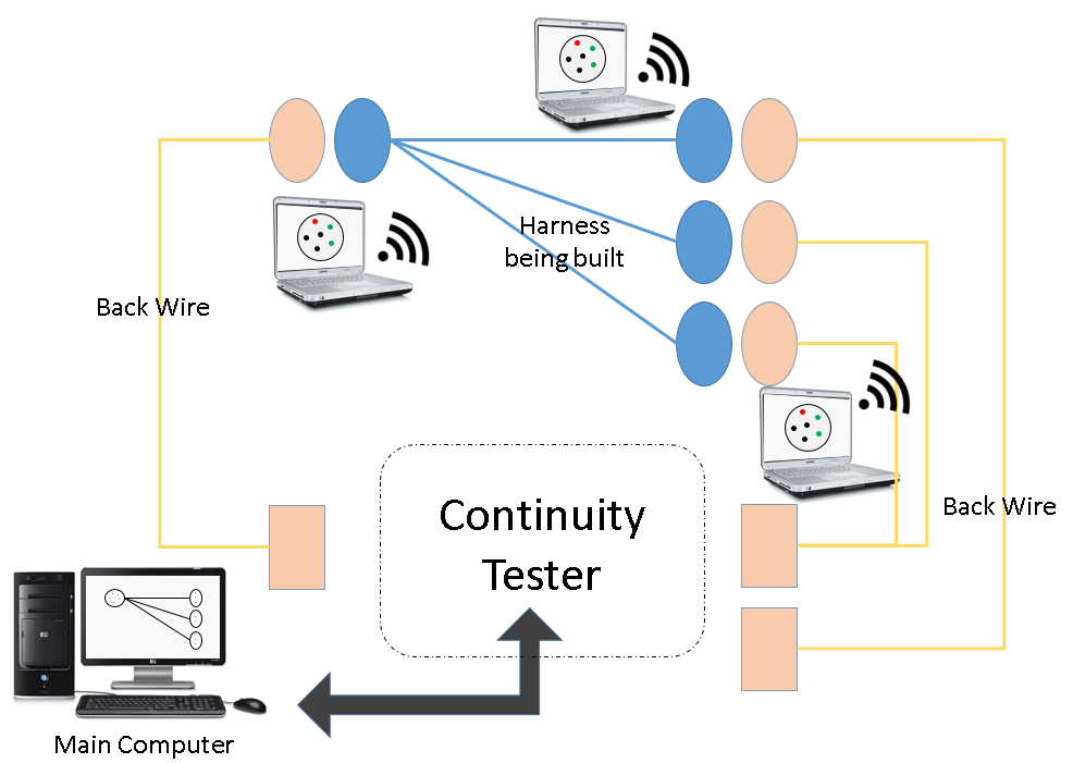
The ideal solution involved having each technician with a ipad or other computer, which would display if the connector was being wired correctly. Back wire harnesses already existed to perform a full continuity test on the completed harness, so it was desirable that the new setup also would use the same back wire, and avoid having to create new and different back wire.
The next step was to figure out how to perform continuity on the cable. Using an off the shelf continuity tester was not an option as none of them provided and open API, that would allow customization to send real time continuity data to multiple computers. The next option considered was to build our own continuity testing hardware, with arrays of relays, just like the commercial versions. The biggest downside was cost. The amount of relays necessary to be able to test a couple hundred pins is large.
In the end it was decided that the continuity tester would be composed of digital input and output hardware. At one end of the harness, a voltage was applied one pin at a time, and at the other end we would read the voltage on all the pins simultaneously and we could determine if any of the pins were connected to the energized pin. The downside to using digital i/o was that there were some limited types of connections that could be not tested and that it was strictly a continuity test, you could not determine resistance of the line or other parameters. But the lower cost and easy of integration made it the right choice.
One end of the harness would be built first, without feedback of course since no continuity could be performed with only one side connected. But as soon as the second end was being built, immediate feed back could be given as to whether each pin was inserted in the correct place. The software would also prompt the technician as to which pin to connect next.
Software was the key ingredient that made everything work. Excel files of the connections of each harness existed, and software was developed to optimized how to wire up the harness to the tester to maximize test coverage.
Comments are disabled